
BEAT inspects lightning protection systems without cutting a cable or disconnecting a conductor. A tuned signal. A drone-mounted sensor. A measurement record you can defend.
PATENTED CONTACT-LESS LPS INSPECTION
A failed continuity test tells you the conductor path is broken. It does not tell you where. That uncertainty means either a full rope-access inspection or a repair decision made without precise information. BEAT changes that. A tuned AC signal is injected into the LPS down conductor. The Field Sensor reads the near field along the blade during flight. Discontinuities appear as measurable changes in the standing wave — localized, documented, and ready for review without a single contact point on the conductor.
Certified and accepted by leading insurance and inspection organizations.
" height="60px" id="VfioOfPPj" stroke-dasharray="" stroke-linecap="butt" stroke-linejoin="miter" stroke-miterlimit="10" stroke-width="1.19" stroke="rgb(218, 218, 218)" width="60.243383268404386px"/><path d="M 39.79 0 L 16.483 0 L 0 16.415 L 0 39.628 L 16.48 56.043 L 39.787 56.043 L 56.267 39.628 L 56.267 16.415 Z" fill="rgb(0, 0, 0)" height="56.043214586931185px" id="gvE5wmqmg" transform="translate(2.048 2.048)" width="56.26731997268962px"/><path d="M 27.008 0 L 11.188 0 L 0 11.143 L 0 26.9 L 11.188 38.042 L 27.008 38.042 L 38.197 26.9 L 38.197 11.143 Z" fill="rgb(255, 255, 255)" height="38.042491666331955px" id="wagJHN96m" transform="translate(11.085 10.964)" width="38.19671472749906px"/><path d="M 0 14.398 L 30.483 14.398 L 30.483 14.998 L 0 14.998 Z M 14.63 18.109 L 14.025 18.109 L 14.025 17.215 L 14.63 17.215 Z M 15.745 17.215 L 15.14 17.215 L 15.14 18.109 L 15.745 18.109 Z M 6.687 21.413 C 6.723 22.664 7.665 23.521 9.224 23.521 C 10.605 23.521 11.547 22.743 11.547 21.618 C 11.557 20.386 10.543 20.054 9.502 19.868 C 8.516 19.697 7.87 19.565 7.87 18.921 C 7.87 18.333 8.364 18.027 9.073 18.027 C 9.834 18.027 10.338 18.456 10.417 19.09 L 11.449 19.09 C 11.403 17.938 10.506 17.16 9.073 17.16 C 7.735 17.16 6.841 17.902 6.841 18.991 C 6.841 20.232 7.827 20.565 8.868 20.741 C 9.863 20.919 10.518 21.061 10.518 21.724 C 10.518 22.321 9.981 22.654 9.237 22.654 C 8.357 22.654 7.783 22.162 7.73 21.43 L 6.689 21.413 Z M 12.408 20.789 C 12.408 22.567 13.251 23.524 14.875 23.524 C 16.499 23.524 17.36 22.567 17.36 20.789 L 17.36 17.215 L 16.328 17.215 L 16.328 20.842 C 16.328 22.003 15.88 22.611 14.875 22.611 C 13.87 22.611 13.439 22.003 13.439 20.842 L 13.439 17.215 L 12.408 17.215 Z M 20.594 23.468 C 22.558 23.468 23.796 22.191 23.796 20.333 C 23.796 18.475 22.56 17.215 20.594 17.215 L 18.459 17.215 L 18.459 23.468 Z M 19.49 18.109 L 20.594 18.109 C 21.974 18.109 22.736 18.994 22.736 20.333 C 22.736 21.673 21.974 22.574 20.594 22.574 L 19.49 22.574 L 19.49 18.107 Z M 30.483 0.002 L 26.343 12.184 L 23.223 12.184 L 19.695 1.851 L 19.695 6.955 C 19.695 10.41 17.977 12.302 14.68 12.302 C 11.384 12.302 9.675 10.408 9.675 6.955 L 9.675 2.268 L 6.135 2.268 L 6.135 12.184 L 3.521 12.184 L 3.521 2.268 L 0 2.268 L 0 0.002 L 12.292 0.002 L 12.292 7.092 C 12.292 9.02 13.008 10.063 14.68 10.063 C 16.352 10.063 17.078 9.022 17.078 7.092 L 17.078 0.002 L 21.835 0.002 L 24.772 9.022 L 27.779 0.002 Z M 13.097 2.265 L 14.299 2.265 L 14.299 0 L 13.097 0 Z M 15.07 2.265 L 16.273 2.265 L 16.273 0 L 15.07 0 Z" fill="rgb(11, 37, 59)" height="23.523839836345815px" id="iGwdtSpT7" transform="translate(14.94 21.447)" width="30.483151933812678px"/></g></svg>)
" width="207.99999767793287px"><path d="M 46.337 0.01 C 44.313 0.154 42.709 1.717 43.634 3.778 C 44.693 6.14 50.833 5.744 49.782 1.834 C 49.398 0.41 47.623 -0.08 46.337 0.01 Z M 22.488 25.152 C 20.896 18.68 19.181 12.182 17.269 5.793 C 16.855 4.407 16.344 1.352 15.058 0.719 C 14.305 0.349 5.324 0.236 4.906 0.53 C 4.593 0.749 4.574 2.026 4.787 2.327 C 5.063 2.715 6.688 2.267 6.99 3.423 L 0 25.152 L 5.503 25.152 C 6.58 24.467 7.128 19.532 7.717 19.136 L 14.525 19.136 C 15.222 19.874 15.975 25.152 16.747 25.152 L 22.484 25.152 Z M 24.949 25.152 L 29.635 25.152 L 29.985 24.798 L 29.985 1.483 C 29.985 1.355 29.542 0.79 29.374 0.685 C 28.833 0.342 24.114 0.274 23.308 0.425 C 22.544 0.568 22.518 1.898 22.827 2.323 C 23.1 2.7 24.412 2.301 24.546 3.894 C 24.583 4.343 24.352 4.78 24.352 5.243 C 24.371 11.715 24.259 18.232 24.483 24.678 C 24.535 24.787 24.87 25.13 24.949 25.152 Z M 32.562 0.425 L 32.662 2.323 C 32.837 2.565 34.202 2.557 34.202 3.367 L 34.202 24.798 L 34.552 25.152 L 39.47 25.152 L 39.82 24.798 L 39.82 1.483 C 39.82 1.378 38.694 0.425 38.53 0.425 L 32.558 0.425 Z M 165.842 4.663 L 174.861 4.663 L 175.211 4.309 L 175.211 0.775 L 174.861 0.421 L 160.571 0.421 L 160.22 0.775 L 160.22 24.561 L 160.571 24.915 L 175.092 24.915 C 175.673 24.463 175.55 21.242 175.222 21.016 L 165.839 20.677 L 165.839 14.555 L 173.921 14.555 L 174.272 14.201 L 174.272 10.668 L 173.921 10.313 L 166.193 10.313 L 165.842 9.959 L 165.842 4.659 Z M 62.01 10.852 C 62.379 11.221 62.834 12.63 62.312 13.03 C 61.939 13.316 57.67 13.907 56.559 14.31 C 53.517 15.414 52.242 17.482 52.5 20.767 C 52.936 26.358 58.822 26.173 62.193 23.269 C 62.804 23.125 62.73 24.241 62.991 24.583 C 63.718 25.548 68.083 25.103 69.347 25.051 C 70.488 23.171 68.15 23.34 67.934 22.206 C 67.475 18.646 69.123 10.061 66.297 7.605 C 63.438 5.119 56.802 6.712 53.67 8.23 C 53.424 8.618 54.524 11.76 55.12 11.704 C 55.512 11.666 56.671 10.965 57.286 10.807 C 58.502 10.494 61.056 9.899 62.01 10.86 Z M 82.455 11.847 L 82.455 24.798 L 82.806 25.152 L 87.723 25.152 L 88.073 24.798 L 88.073 9.963 C 88.073 8.75 86.765 7.194 85.628 6.769 C 82.802 5.714 79.976 6.965 77.884 8.897 C 77.206 8.159 77.829 7.236 76.736 6.761 C 76.032 6.456 70.876 6.381 70.611 6.769 C 70.439 7.021 70.436 7.978 70.54 8.283 C 70.734 8.852 72.382 8.633 72.382 10.197 L 72.382 24.798 L 72.732 25.152 L 77.418 25.152 L 77.769 24.798 L 77.769 12.789 C 77.769 11.481 82.131 10.031 82.455 11.847 Z M 189.497 11.726 C 189.702 10.185 191.555 8.78 189.896 7.677 C 186.72 5.567 179.636 5.654 177.906 9.605 C 176.758 12.227 177.291 14.891 179.733 16.48 C 181.116 17.381 187.137 18.379 185.158 20.666 C 184.047 21.95 179.867 20.839 178.622 19.735 C 178.246 19.818 177.079 23.031 177.355 23.468 C 182.503 26.712 192.141 25.804 190.892 17.746 C 190.653 16.202 189.441 15.271 188.177 14.585 C 187.003 13.949 182.79 12.981 182.787 11.609 C 184.024 8.95 187.585 10.788 189.497 11.726 Z M 44.275 9.726 L 44.275 24.798 L 44.626 25.152 L 49.312 25.152 L 49.662 24.798 L 49.662 7.609 C 49.662 6.14 43.858 6.569 42.784 6.58 C 42.243 6.75 42.277 8.136 42.504 8.449 C 42.706 8.728 44.044 8.618 44.275 9.73 Z M 98.147 10.313 C 98.229 10.675 98.065 10.867 97.927 11.154 C 97.151 12.8 90.884 20.421 90.884 21.027 L 90.884 24.794 L 91.235 25.148 L 104.585 25.148 C 105.443 25.148 104.913 23.517 104.913 23.148 C 104.913 22.779 105.428 21.381 104.82 21.381 L 97.793 21.381 L 97.431 20.79 C 97.987 19.306 104.701 11.063 104.701 10.43 L 104.701 6.897 C 104.496 6.561 104.235 6.573 103.892 6.531 C 101.457 6.245 95.843 6.32 93.33 6.531 C 89.882 6.825 90.959 9.003 90.981 11.734 L 92.722 11.922 C 92.816 11.417 93.222 10.306 93.807 10.306 L 98.139 10.306 Z" fill="rgb(255, 255, 255)" height="25.263781468374997px" id="l9PSCZGtU" transform="translate(0 4.897)" width="191.00213729443783px"/><path d="M 134.917 0 C 136.148 0.58 137.512 0.678 138.847 1.115 C 155.437 6.532 155.146 32.22 137.781 37.144 C 115.609 43.427 104.805 13.415 122.342 2.784 C 124.728 1.337 127.163 0.855 129.765 0.004 L 134.917 0.004 Z M 129.709 3.123 C 110.591 5.541 113.153 38.078 135.011 34.827 C 154.285 31.96 151.698 0.343 129.709 3.123 Z M 208 15.543 L 208 29.907 L 202.844 29.907 C 202.796 29.271 203.083 28.483 202.494 28.027 C 199.131 31.614 192.498 31.022 192.517 25.082 C 192.536 19.672 197.815 18.35 202.225 18.572 C 202.96 18.331 202.602 16.805 202.247 16.259 C 200.853 14.104 196.536 16.104 194.638 16.621 L 193.546 13.535 C 196.256 11.128 203.974 10.164 206.565 12.861 C 207.418 13.75 207.355 14.609 207.996 15.543 Z M 202.617 21.898 C 200.987 21.797 198.56 21.83 198.042 23.778 C 197.095 27.346 202.326 26.95 202.628 24.622 C 202.736 23.789 202.527 22.765 202.617 21.902 Z M 22.484 30.145 L 16.747 30.145 C 15.975 30.145 15.222 24.867 14.525 24.136 L 7.717 24.136 C 7.128 24.524 6.58 29.463 5.503 30.145 L 0 30.145 L 6.99 8.416 C 6.688 7.259 5.063 7.708 4.787 7.32 C 4.571 7.018 4.593 5.741 4.906 5.523 C 5.324 5.229 14.305 5.338 15.058 5.711 C 16.348 6.344 16.855 9.399 17.269 10.785 C 19.181 17.174 20.896 23.676 22.488 30.145 Z M 9.018 20.252 L 13.47 20.252 C 13.686 20.083 13.775 20.007 13.783 19.717 C 13.794 19.209 12.556 15.016 12.303 14.127 C 12.128 13.516 11.788 11.55 11.132 11.535 L 8.709 19.487 C 8.586 19.759 8.787 20.18 9.022 20.252 Z M 165.839 9.655 L 165.839 14.955 L 166.189 15.31 L 173.917 15.31 L 174.268 15.664 L 174.268 19.197 L 173.917 19.551 L 165.835 19.551 L 165.835 25.673 L 175.219 26.012 C 175.547 26.242 175.666 29.459 175.088 29.911 L 160.567 29.911 L 160.217 29.557 L 160.217 5.771 L 160.567 5.417 L 174.857 5.417 L 175.207 5.771 L 175.207 9.305 L 174.857 9.659 L 165.839 9.659 Z M 82.451 16.839 C 82.131 15.023 77.765 16.474 77.765 17.781 L 77.765 29.79 L 77.415 30.145 L 72.728 30.145 L 72.378 29.79 L 72.378 15.189 C 72.378 13.626 70.73 13.84 70.536 13.275 C 70.432 12.97 70.436 12.013 70.607 11.761 C 70.876 11.373 76.028 11.448 76.732 11.753 C 77.825 12.228 77.198 13.151 77.881 13.889 C 79.976 11.957 82.798 10.706 85.624 11.761 C 86.761 12.187 88.07 13.739 88.07 14.955 L 88.07 29.79 L 87.719 30.145 L 82.802 30.145 L 82.451 29.79 Z M 62.006 15.845 C 61.052 14.884 58.498 15.479 57.283 15.792 C 56.668 15.95 55.508 16.651 55.117 16.688 C 54.52 16.745 53.42 13.607 53.666 13.215 C 56.798 11.697 63.434 10.103 66.294 12.59 C 69.12 15.046 67.475 23.631 67.93 27.191 C 68.147 28.325 70.484 28.156 69.343 30.035 C 68.079 30.088 63.714 30.533 62.987 29.568 C 62.726 29.225 62.8 28.11 62.189 28.253 C 58.819 31.154 52.932 31.342 52.496 25.752 C 52.239 22.467 53.514 20.399 56.556 19.295 C 57.663 18.892 61.932 18.301 62.308 18.014 C 62.83 17.615 62.372 16.21 62.006 15.837 Z M 62.234 25.131 C 62.659 24.592 62.789 21.397 62.159 21.213 C 61.384 20.987 58.289 22.234 57.961 23.3 C 56.843 26.939 60.608 27.184 62.237 25.127 Z M 98.143 15.306 L 93.811 15.306 C 93.226 15.306 92.819 16.417 92.726 16.922 L 90.985 16.734 C 90.963 14.002 89.885 11.821 93.334 11.531 C 95.847 11.316 101.457 11.241 103.896 11.531 C 104.235 11.573 104.5 11.561 104.705 11.897 L 104.705 15.43 C 104.705 16.063 97.99 24.306 97.435 25.79 L 97.796 26.381 L 104.824 26.381 C 105.435 26.381 104.917 27.783 104.917 28.148 C 104.917 28.513 105.443 30.148 104.589 30.148 L 91.239 30.148 L 90.888 29.794 L 90.888 26.027 C 90.888 25.421 97.155 17.796 97.931 16.153 C 98.065 15.867 98.233 15.675 98.151 15.313 Z M 189.494 16.719 C 187.581 15.78 184.021 13.942 182.783 16.602 C 182.783 17.973 186.999 18.941 188.174 19.578 C 189.434 20.263 190.646 21.194 190.888 22.738 C 192.141 30.792 182.5 31.704 177.351 28.461 C 177.075 28.024 178.242 24.81 178.619 24.727 C 179.864 25.831 184.039 26.942 185.154 25.658 C 187.134 23.371 181.113 22.373 179.73 21.473 C 177.284 19.883 176.751 17.216 177.903 14.598 C 179.636 10.646 186.72 10.559 189.892 12.669 C 191.551 13.773 189.699 15.174 189.494 16.719 Z M 32.558 5.417 L 38.53 5.417 C 38.694 5.417 39.82 6.37 39.82 6.476 L 39.82 29.79 L 39.47 30.145 L 34.552 30.145 L 34.202 29.79 L 34.202 8.359 C 34.202 7.549 32.841 7.557 32.662 7.316 L 32.562 5.417 Z M 24.945 30.145 C 24.867 30.122 24.531 29.779 24.479 29.67 C 24.255 23.228 24.367 16.707 24.348 10.235 C 24.348 9.772 24.58 9.335 24.542 8.887 C 24.404 7.297 23.096 7.696 22.824 7.316 C 22.518 6.89 22.544 5.557 23.305 5.417 C 24.11 5.266 28.83 5.334 29.37 5.677 C 29.538 5.783 29.982 6.348 29.982 6.476 L 29.982 29.79 L 29.631 30.145 Z M 44.272 14.718 C 44.04 13.611 42.702 13.72 42.501 13.437 C 42.277 13.125 42.24 11.738 42.78 11.569 C 43.85 11.558 49.659 11.128 49.659 12.597 L 49.659 29.787 L 49.308 30.141 L 44.622 30.141 L 44.272 29.787 L 44.272 14.714 Z M 46.333 5.003 C 47.619 4.912 49.394 5.402 49.778 6.826 C 50.829 10.736 44.689 11.132 43.63 8.77 C 42.706 6.709 44.309 5.146 46.333 5.003 Z" fill="rgb(0, 0, 0)" height="38px" id="WvIAt2N7s" transform="translate(0 0)" width="207.99998882299786px"/><path d="M 7.728 2.942 C 7.594 2.192 6.729 2.113 6.099 2.11 L 6.088 0 L 12.061 0 C 12.12 0 12.881 0.765 12.881 0.825 L 12.881 22.727 L 12.53 23.081 L 8.079 23.081 L 7.728 22.727 L 7.728 2.946 Z M 15.461 4.826 C 15.658 4.182 19.949 4.347 20.4 5.097 C 20.412 5.519 20.848 6.438 20.848 6.709 L 20.848 22.723 L 20.497 23.077 L 15.811 23.077 L 15.461 22.723 Z M 0 5.767 C 0.321 4.23 4.093 4.117 5.152 4.826 L 5.152 22.723 L 4.802 23.077 L 0.35 23.077 L 0 22.723 Z" fill="rgb(0, 0, 0)" height="23.08118822081741px" id="AX411Fm5L" transform="translate(122.096 6.592)" width="20.847719559797042px"/></g></svg>)
" width="183.99998542548158px"><path d="M 0.003 47.982 C 0.593 46.813 1.347 45.721 2.205 44.73 C 4.215 42.406 7.205 39.594 9.486 37.465 C 12.899 34.279 16.562 31.345 20.32 28.581 L 12.749 29.632 C 10.913 29.464 5.01 30.281 4.176 28.246 C 3.342 26.212 5.722 25.727 7.184 25.612 C 10.107 25.382 14.008 25.608 16.911 26.055 C 17.846 26.198 22.057 27.029 22.608 27.444 C 23.208 27.89 24.171 33.124 24.314 34.154 C 24.695 36.903 25.124 41.914 24.402 44.51 C 23.903 46.304 21.956 46.817 21.126 45.17 C 20.295 43.523 20.518 38.456 20.7 36.422 L 21.754 29.827 C 17.263 35.557 12.316 41.475 6.901 46.363 C 5.394 47.724 1.786 51.423 0 49.134 L 0 47.986 Z M 2.111 0 C 3.754 0.754 5.181 1.951 6.521 3.151 C 10.725 6.912 15.184 12.042 18.558 16.571 C 18.962 17.115 22.469 21.931 22.232 22.175 C 21.192 21.805 20.204 21.044 19.297 20.42 C 15.369 17.719 11.534 14.627 8.046 11.379 C 5.125 8.657 1.943 5.579 0 2.104 L 0 0 L 2.107 0 Z M 49.069 0 C 50.042 0.646 50.223 1.141 49.944 2.306 C 49.138 5.66 36.487 16.295 33.222 18.696 C 32.447 19.265 28.662 22.067 28.083 22.175 C 27.796 22.227 27.744 22.171 27.796 21.889 C 30.772 17.531 33.94 13.287 37.471 9.362 C 39.069 7.582 40.995 5.534 42.743 3.915 C 44.324 2.446 46.03 1.054 47.921 0 L 49.072 0 Z M 79.255 1.72 C 82.576 2.167 84.244 5.573 83.086 8.598 C 82.611 9.837 81.634 10.29 80.692 11.086 C 84.349 11.874 84.966 17.021 82.318 19.303 C 81.275 20.2 79.07 20.835 77.723 20.835 L 68.429 20.835 L 68.429 1.72 L 79.258 1.72 Z M 77.915 4.589 C 76.118 4.292 73.571 4.808 71.687 4.589 L 71.687 9.557 L 77.915 9.557 C 77.992 9.557 79.178 9.027 79.293 8.926 C 80.71 7.68 79.879 4.913 77.915 4.589 Z M 71.684 17.778 L 78.104 17.778 C 79.37 17.778 80.514 16.267 80.483 15.025 C 80.452 13.783 79.171 12.426 77.915 12.426 L 71.687 12.426 L 71.687 17.778 Z M 82.036 41.101 L 77.339 41.101 L 77.053 40.815 L 77.053 38.044 L 85.486 38.044 L 85.486 47.986 L 82.227 47.986 L 82.227 45.693 C 76.97 51.531 67.856 47.225 67.27 39.869 C 66.974 36.171 67.916 32.835 70.934 30.511 C 74.974 27.402 82.534 28.068 84.897 32.96 L 82.126 34.803 L 81.844 34.709 C 77.123 28.4 69.046 33.623 71.248 40.874 C 72.891 46.29 80.438 46.593 82.039 41.105 Z M 114.619 6.693 L 114.619 8.605 L 116.21 7.038 C 118.439 5.848 121.872 6.187 122.867 8.797 L 123.261 8.675 C 126.174 4.641 132.161 5.935 132.632 11.19 C 132.824 13.308 132.887 18.12 132.646 20.182 C 132.615 20.462 132.622 20.674 132.35 20.842 L 129.569 20.842 L 129.569 12.143 C 129.569 12.08 129.332 11.03 129.286 10.897 C 128.358 8.172 123.98 8.685 123.627 11.763 C 123.327 14.373 123.941 17.59 123.638 20.182 C 123.606 20.462 123.613 20.674 123.341 20.842 L 120.561 20.842 L 120.561 11.955 C 120.561 11.892 120.281 10.911 120.219 10.765 C 119.357 8.647 116.192 8.601 115.118 10.538 C 115.034 10.688 114.619 11.696 114.619 11.763 L 114.619 20.842 L 111.552 20.842 L 111.552 6.696 L 114.619 6.696 Z M 180.933 20.647 L 180.933 18.542 C 176.774 24.066 169.339 19.935 169.416 13.668 C 169.482 8.399 175.627 3.786 179.845 7.677 C 180.291 8.088 180.494 8.633 180.93 8.982 L 180.93 6.689 L 184 6.689 L 184 20.643 L 180.933 20.643 Z M 176.286 9.418 C 171.171 10.081 171.796 18.291 176.994 18.166 C 182.294 18.04 182.189 8.654 176.286 9.418 Z M 97.08 20.838 C 96.571 20.681 96.867 19.017 96.79 18.546 L 95.737 19.882 C 89.244 23.996 83.34 16.787 86.156 10.329 C 88.012 6.071 93.94 4.805 96.79 8.797 L 96.79 6.693 L 99.857 6.693 L 99.857 20.838 L 97.076 20.838 Z M 92.147 9.418 C 86.425 10.151 88.351 20.224 94.372 17.754 C 98.472 16.072 97.247 8.765 92.147 9.418 Z M 138.766 47.982 L 138.766 45.882 C 138.386 46.056 138.239 46.656 137.932 46.96 C 135.259 49.566 130.64 48.436 128.721 45.484 C 124.855 39.534 130.075 31.108 137.105 34.443 L 138.762 36.132 L 138.762 34.032 L 141.833 34.032 L 141.833 47.986 L 138.766 47.986 Z M 133.923 36.75 C 129.59 37.486 129.649 44.699 133.895 45.288 C 140.625 46.227 140.182 35.686 133.923 36.75 Z M 147.966 14.722 L 137.618 14.722 C 137.925 18.836 143.301 19.369 145.384 16.25 L 147.551 18.064 C 143.814 23.267 135.04 21.522 134.363 14.816 C 133.225 3.542 149.302 3.723 147.97 14.722 Z M 144.707 12.234 C 144.16 8.116 138.406 8.326 137.614 12.234 Z M 157.358 42.054 L 147.01 42.054 C 147.436 46.056 152.62 46.674 154.784 43.586 L 156.968 45.386 C 153.897 49.497 147.261 49.455 144.676 44.856 C 142.475 40.944 144.125 35.099 148.73 33.927 C 154.082 32.563 158.136 36.886 157.355 42.054 Z M 154.1 39.569 C 153.597 35.427 147.67 35.553 147.007 39.569 Z M 116.342 28.864 L 116.342 35.745 C 118.631 32.926 123.641 32.751 125.194 36.377 C 125.323 36.68 125.731 37.908 125.731 38.132 L 125.731 47.975 L 122.664 47.975 L 122.664 39.088 C 122.664 38.941 122.249 37.919 122.131 37.71 C 120.986 35.721 117.553 36.139 116.681 38.282 C 116.621 38.428 116.339 39.405 116.339 39.472 L 116.339 47.979 L 113.272 47.979 L 113.272 28.864 L 116.339 28.864 Z" fill="rgb(35, 31, 32)" height="49.86425838752558px" id="B_rYsG83k" transform="translate(0 0)" width="183.99998540716572px"/><path d="M 65.898 27.347 C 75.827 26.209 76.982 41.077 67.737 41.988 C 57.667 42.982 56.603 28.411 65.898 27.347 Z M 66.083 30.403 C 61.683 31.007 61.634 38.188 65.887 38.907 C 72.461 40.02 72.513 29.521 66.083 30.403 Z M 0.009 21.369 C 0.156 21.223 2.615 22.898 2.943 23.125 C 8.089 26.638 18.043 34.681 21.327 39.772 C 23.511 43.16 21.609 44.706 18.347 42.553 C 13.459 39.322 6.216 30.511 2.727 25.637 C 2.416 25.204 -0.172 21.554 0.009 21.373 Z M 122.094 14.488 L 122.094 0.342 L 125.161 0.342 L 125.161 2.255 C 125.531 1.965 125.712 1.543 126.117 1.204 C 128.716 -0.983 133.175 -0.139 134.159 3.319 C 135.073 6.543 134.354 10.95 134.47 14.31 C 134.267 14.597 131.581 14.597 131.378 14.31 L 131.211 4.729 C 130.649 2.3 126.825 2.213 125.653 4.184 C 124.554 6.034 125.451 11.428 125.168 13.832 C 125.137 14.111 125.144 14.324 124.871 14.492 L 122.091 14.492 Z" fill="rgb(35, 31, 32)" height="43.54480927869165px" id="nEgKeVtfa" transform="translate(27.737 6.455)" width="134.63009508143708px"/><path d="M 84.799 33.109 L 88.25 33.109 L 88.25 35.785 L 84.799 35.785 L 84.799 42.572 C 84.799 42.642 85.13 43.563 85.207 43.696 C 85.874 44.854 87.112 44.568 88.25 44.582 L 88.25 47.258 C 86.216 47.684 83.393 47.454 82.339 45.409 C 82.21 45.161 81.732 43.884 81.732 43.72 L 81.732 35.789 L 79.241 35.789 L 79.241 33.112 L 81.732 33.112 L 81.732 30.052 L 84.799 29.096 Z M 5.642 24.312 C 5.565 23.88 5.666 24.009 5.886 23.887 C 6.434 23.587 7.627 23.381 8.29 23.227 C 12.41 22.275 17.822 21.72 22.036 22.013 C 23.104 22.086 25.351 22.33 25.811 23.409 C 26.635 25.331 24.004 25.931 22.609 26.043 C 16.96 26.486 11.106 25.589 5.638 24.316 Z M 86.906 5.581 L 86.906 8.83 C 85.476 8.739 83.473 8.875 82.842 10.414 C 82.775 10.575 82.496 11.524 82.496 11.601 L 82.496 19.916 L 79.43 19.916 L 79.43 5.77 L 82.496 5.77 C 82.517 6.374 82.465 6.984 82.496 7.588 C 82.507 7.804 82.371 8.111 82.685 8.062 C 83.17 6.258 85.151 5.403 86.903 5.578 Z M 143.832 32.917 L 143.832 36.166 C 142.454 36.12 140.615 36.064 139.834 37.432 C 139.757 37.565 139.425 38.483 139.425 38.556 L 139.425 47.063 L 136.359 47.063 L 136.359 33.109 L 139.425 33.109 C 139.45 33.709 139.391 34.327 139.425 34.927 C 139.436 35.143 139.3 35.45 139.614 35.401 C 139.977 33.479 142.042 32.704 143.832 32.917 Z M 2.003 20.683 C 0.66 16.025 -0.282 10.735 0.077 5.861 C 0.143 4.946 0.377 2.86 1.284 2.476 C 3.381 1.586 3.988 3.655 4.117 5.288 C 4.424 9.189 3.985 14.022 3.06 17.819 C 2.997 18.077 2.317 20.924 2.006 20.683 Z M 141.721 5.773 L 144.788 5.773 L 144.788 19.727 L 141.721 19.727 Z M 142.625 0.079 C 145.657 -0.612 145.992 3.463 143.494 3.823 C 140.995 4.182 140.598 0.539 142.625 0.079 Z" fill="rgb(35, 31, 32)" height="47.437011142942275px" id="uJf4JAe69" transform="translate(22.853 1.047)" width="145.15748620396934px"/></g></svg>)
" width="212.00000522421078px"><path d="M 45.637 0.016 C 43.348 0.243 43.527 3.739 45.868 3.713 C 48.368 3.681 48.214 -0.237 45.637 0.016 Z M 50.976 0.016 C 48.8 0.264 48.902 3.649 51.166 3.702 C 53.738 3.76 53.64 -0.285 50.976 0.016 Z M 18.758 0.196 L 0 0.196 L 0 19.386 L 18.758 19.386 Z M 117.558 1.241 L 114.314 1.241 L 114.314 16.909 L 117.363 16.909 L 117.363 15.996 C 119.109 17.723 121.906 17.633 123.498 15.737 C 125.695 13.128 125.474 6.77 122.153 5.17 C 120.952 4.589 119.247 4.6 118.138 5.408 C 117.928 5.561 117.789 5.814 117.548 5.878 L 117.548 1.241 Z M 192.518 1.241 L 189.212 1.241 L 189.212 16.909 L 192.518 16.909 L 192.518 8.782 C 192.518 8.698 192.898 8.249 192.996 8.159 C 193.771 7.446 195.265 7.372 195.855 8.36 C 195.999 8.603 196.21 9.294 196.21 9.564 L 196.21 16.909 L 199.516 16.909 C 199.433 14.459 199.623 11.94 199.516 9.495 C 199.428 7.504 199.043 5.492 196.908 4.927 C 195.362 4.515 193.668 4.742 192.518 5.941 Z M 69.046 5.028 L 69.046 1.928 L 68.949 1.827 L 65.74 1.827 L 65.74 5.028 L 64.344 5.028 L 64.344 7.737 L 64.441 7.837 L 65.745 7.837 L 65.745 14.464 C 65.745 14.702 65.982 15.436 66.094 15.668 C 67.034 17.659 69.883 17.39 71.593 16.777 L 71.593 13.968 C 70.879 14.221 69.678 14.765 69.205 13.841 C 69.175 13.778 69.051 13.45 69.051 13.413 L 69.051 7.832 L 71.31 7.832 L 71.408 7.731 L 71.408 5.123 L 71.31 5.022 L 69.051 5.022 Z M 77.696 1.827 L 74.488 1.827 L 74.39 1.928 L 74.39 5.028 L 73.086 5.028 L 72.989 5.128 L 72.989 7.737 L 73.086 7.837 L 74.39 7.837 L 74.39 14.137 C 74.39 14.955 74.837 16.043 75.468 16.556 C 76.654 17.517 79.011 17.358 80.304 16.682 L 80.304 13.973 C 79.539 14.216 78.24 14.813 77.835 13.73 C 77.809 13.656 77.696 13.26 77.696 13.223 L 77.696 7.837 L 79.955 7.837 L 80.053 7.737 L 80.053 5.028 L 77.701 5.028 L 77.701 1.827 Z M 63.199 4.895 C 61.685 4.536 60.217 4.822 59.323 6.2 L 59.323 5.022 L 56.274 5.022 L 56.274 16.904 L 59.58 16.904 L 59.58 8.972 C 59.58 8.972 59.79 8.64 59.837 8.582 C 60.622 7.573 62.126 7.752 63.204 8.09 L 63.204 4.89 Z M 91.998 11.945 C 92.291 9.257 91.542 5.994 88.775 5.043 C 83.22 3.137 80.289 9.564 82.219 14.19 C 83.764 17.892 89.057 18.156 91.547 15.362 L 89.683 13.123 C 88.333 14.876 85.063 14.908 84.95 12.167 C 84.95 12.093 84.976 11.951 85.042 11.951 L 92.004 11.951 Z M 111.136 16.904 L 111.136 8.972 C 110.982 6.966 110.397 5.265 108.277 4.853 C 106.537 4.515 104.843 4.943 103.662 6.327 C 102.548 4.494 99.483 4.288 97.887 5.492 C 97.65 5.672 97.486 5.983 97.209 6.068 L 97.209 5.022 L 94.252 5.022 L 94.154 5.123 L 94.154 16.904 L 97.46 16.904 L 97.46 8.777 C 97.46 8.56 98.159 7.927 98.369 7.821 C 99.042 7.478 100.135 7.562 100.602 8.228 C 100.802 8.518 101.018 9.284 101.018 9.627 L 101.018 16.904 L 104.324 16.904 C 104.288 14.522 104.375 12.136 104.324 9.754 C 104.309 9.052 104.047 8.782 104.647 8.196 C 105.479 7.388 107.101 7.346 107.594 8.55 C 107.661 8.708 107.82 9.221 107.82 9.363 L 107.82 16.904 L 111.126 16.904 Z M 136.953 11.945 C 137.43 8.069 135.659 4.415 131.393 4.763 C 125.597 5.239 124.894 15.346 130.218 16.936 C 132.461 17.606 134.992 17.126 136.573 15.304 L 134.689 13.186 C 134.34 13.419 134.042 13.751 133.667 13.952 C 131.932 14.892 129.853 14.174 129.961 11.94 L 136.953 11.94 Z M 146.106 4.895 C 144.602 4.547 143.113 4.811 142.23 6.2 L 142.23 5.022 L 139.181 5.022 L 139.181 16.904 L 142.425 16.904 L 142.425 9.104 C 142.425 9.073 142.667 8.687 142.718 8.618 C 143.514 7.562 145.007 7.752 146.116 8.09 L 146.116 4.89 Z M 175.28 6.147 C 173.545 5.028 171.414 4.436 169.376 4.927 C 165.855 5.777 165.3 10.34 168.699 11.829 C 169.607 12.225 171.055 12.389 171.825 12.859 C 172.595 13.329 172.184 14.327 171.317 14.427 C 169.864 14.596 168.355 13.794 167.154 13.054 C 167.087 13.429 165.983 15.542 166.101 15.732 C 166.255 15.98 167.718 16.619 168.057 16.73 C 171.24 17.797 176.091 17.258 175.532 12.711 C 175.177 9.865 172.205 9.849 170.311 8.999 C 169.279 8.534 169.772 7.525 170.855 7.525 C 172.025 7.525 173.067 8.185 174.084 8.682 L 175.285 6.147 Z M 185.08 12.727 C 184.13 14.855 181.456 15.008 180.737 12.579 C 180.167 10.646 180.568 7.319 183.196 7.642 C 184.053 7.747 184.654 8.46 185.075 9.173 L 185.162 9.194 L 187.272 7.436 C 187.349 7.267 186.923 6.77 186.795 6.617 C 184.243 3.596 179.315 4.304 177.754 7.98 C 176.779 10.271 177.02 13.514 178.653 15.436 C 180.506 17.617 184.151 17.849 186.256 15.927 C 186.466 15.732 187.344 14.771 187.308 14.533 Z M 28.358 5.028 L 25.052 5.028 L 28.558 16.899 L 31.53 16.899 L 33.507 9.791 L 35.699 16.909 L 38.594 16.909 L 42.028 5.022 L 38.82 5.022 L 37.008 12.009 L 34.944 5.086 L 32.27 5.017 L 30.108 12.009 L 28.358 5.022 Z M 50.293 5.028 L 50.293 12.632 C 50.293 12.949 50.006 13.699 49.785 13.936 C 49.174 14.591 47.588 14.496 47.105 13.688 C 47.028 13.556 46.797 12.943 46.797 12.827 L 46.797 5.123 L 46.7 5.022 L 43.491 5.022 L 43.491 13.017 C 43.491 14.639 44.775 16.26 46.207 16.82 C 49.472 18.092 53.589 16.593 53.599 12.563 L 53.599 5.022 L 50.288 5.022 Z M 163.971 5.028 L 160.726 5.028 L 160.726 16.909 L 163.971 16.909 Z" fill="rgb(255, 255, 255)" height="19.386109920908794px" id="dDjPiZHO7" transform="translate(0 0.205)" width="199.54958805072818px"/><path d="M 151.512 20.964 C 150.998 20.917 150.156 20.669 149.653 20.489 C 148.924 20.23 148.247 19.84 147.574 19.454 L 148.621 17.046 L 148.734 16.988 C 149.956 17.775 151.296 18.208 152.754 18.092 C 154.361 17.965 154.453 16.729 154.438 15.346 L 153.632 15.921 C 148.442 17.965 145.957 12.188 147.605 7.841 C 148.74 4.842 152.379 3.95 154.628 6.21 L 154.628 5.233 L 157.677 5.233 L 157.677 16.56 C 157.677 16.94 157.307 18.113 157.138 18.482 C 156.476 19.908 154.925 20.806 153.421 20.964 C 152.944 21.012 151.994 21.012 151.512 20.964 Z M 152.194 7.857 C 150.321 8.137 150.115 11.221 150.947 12.563 C 151.779 13.904 153.678 13.714 154.417 12.425 L 154.427 8.919 C 154.048 8.058 153.072 7.725 152.189 7.857 Z M 211.975 10.255 C 212 10.672 212.016 11.348 211.975 11.755 C 211.97 11.829 211.846 12.003 211.913 12.145 L 204.947 12.203 C 204.895 15.071 208.212 15.134 209.654 13.318 L 211.523 15.515 C 209.197 18.276 204.018 18.107 202.318 14.712 C 200.547 11.163 201.974 5.312 206.41 4.963 C 209.747 4.705 211.651 6.843 211.908 10.091 C 211.913 10.176 211.975 10.239 211.975 10.25 Z M 208.797 9.737 C 208.9 6.981 204.967 7.07 204.921 9.737 Z M 162.508 0.01 C 164.936 0.269 164.761 3.965 162.292 3.918 C 159.931 3.876 159.746 0.337 162.128 0.01 C 162.231 -0.006 162.405 -0.001 162.508 0.01 Z M 18.758 0.401 L 18.758 19.591 L 0 19.591 L 0 0.401 Z M 3.054 10.651 L 1.022 10.651 L 2.618 17.173 L 4.805 17.12 L 5.693 12.937 L 6.71 17.183 L 8.075 17.183 C 7.736 16.307 8.178 15.816 8.768 15.25 C 8.126 14.559 8.414 13.297 9.441 13.334 C 10.467 13.371 10.719 14.87 9.795 15.298 L 10.401 16.08 L 10.632 15.567 L 11.191 15.557 C 11.181 15.847 10.796 16.428 10.904 16.666 C 10.929 16.719 11.371 17.162 11.427 17.178 C 11.535 17.21 12.074 17.215 12.151 17.162 L 13.07 12.948 L 14.02 17.13 L 16.212 17.189 L 17.808 10.667 L 15.775 10.667 L 14.949 14.907 L 13.994 10.667 L 12.254 10.667 L 11.294 14.971 L 10.431 10.667 L 8.398 10.667 L 7.541 14.971 L 6.581 10.661 L 4.841 10.672 L 3.881 14.907 L 3.054 10.667 Z M 9.112 13.999 C 8.655 14.469 9.492 15.446 9.764 14.569 C 9.939 14.02 9.461 13.635 9.112 13.999 Z M 9.194 15.747 C 8.008 16.571 9.235 17.901 10.036 16.703 Z M 111.136 17.109 L 107.83 17.109 L 107.83 9.568 C 107.83 9.426 107.671 8.913 107.604 8.755 C 107.112 7.551 105.484 7.593 104.658 8.401 C 104.057 8.987 104.324 9.257 104.334 9.959 C 104.381 12.341 104.293 14.728 104.334 17.109 L 101.028 17.109 L 101.028 9.832 C 101.028 9.489 100.813 8.723 100.612 8.433 C 100.15 7.768 99.052 7.683 98.379 8.026 C 98.164 8.137 97.471 8.766 97.471 8.982 L 97.471 17.109 L 94.165 17.109 L 94.165 5.328 L 94.262 5.227 L 97.219 5.227 L 97.219 6.273 C 97.496 6.189 97.661 5.877 97.897 5.697 C 99.493 4.493 102.553 4.699 103.672 6.532 C 104.853 5.148 106.547 4.726 108.287 5.058 C 110.407 5.47 110.993 7.171 111.147 9.178 L 111.147 17.109 Z M 28.358 5.233 L 30.103 12.214 L 32.264 5.227 L 34.939 5.296 L 37.003 12.214 L 38.815 5.233 L 42.028 5.233 L 38.589 17.109 L 35.699 17.115 L 33.507 9.996 L 31.53 17.104 L 28.558 17.104 L 25.052 5.233 Z M 117.558 1.446 L 117.558 6.083 C 117.794 6.02 117.938 5.766 118.149 5.613 C 119.258 4.805 120.957 4.794 122.163 5.375 C 125.485 6.981 125.7 13.334 123.508 15.942 C 121.912 17.838 119.119 17.928 117.374 16.201 L 117.374 17.115 L 114.324 17.115 L 114.324 1.446 L 117.569 1.446 Z M 119.068 7.857 C 118.518 7.937 117.82 8.343 117.569 8.866 L 117.558 13.487 C 118.349 14.78 120.197 15.008 121.044 13.608 C 122.071 11.913 121.824 7.472 119.068 7.857 Z M 192.518 1.446 L 192.518 6.146 C 193.668 4.948 195.357 4.726 196.908 5.132 C 199.043 5.697 199.428 7.709 199.516 9.7 C 199.623 12.14 199.433 14.664 199.516 17.115 L 196.21 17.115 L 196.21 9.769 C 196.21 9.5 195.999 8.808 195.855 8.565 C 195.265 7.577 193.776 7.651 192.996 8.364 C 192.904 8.449 192.518 8.903 192.518 8.987 L 192.518 17.115 L 189.212 17.115 L 189.212 1.446 Z M 91.998 12.151 L 85.037 12.151 C 84.971 12.151 84.94 12.293 84.945 12.367 C 85.058 15.108 88.328 15.076 89.678 13.323 L 91.542 15.562 C 89.052 18.35 83.759 18.092 82.214 14.39 C 80.284 9.764 83.215 3.337 88.769 5.243 C 91.542 6.194 92.286 9.463 91.993 12.145 Z M 88.821 9.737 C 88.939 6.981 85.012 7.07 84.945 9.737 Z" fill="rgb(0, 0, 0)" height="21px" id="WHnwNNzo3" width="212.00000522421078px"/><path d="M 93.461 11.945 L 86.47 11.945 C 86.367 14.179 88.441 14.897 90.176 13.957 C 90.546 13.757 90.848 13.424 91.198 13.192 L 93.082 15.309 C 91.495 17.131 88.97 17.612 86.726 16.941 C 81.403 15.352 82.106 5.244 87.902 4.769 C 92.168 4.42 93.944 8.069 93.461 11.951 Z M 90.345 9.532 C 90.371 6.765 86.475 6.876 86.47 9.532 Z M 6.802 5.028 L 10.108 5.028 L 10.108 12.569 C 10.098 16.603 5.986 18.098 2.716 16.825 C 1.278 16.265 0 14.644 0 13.023 L 0 5.028 L 3.208 5.028 L 3.306 5.128 L 3.306 12.833 C 3.306 12.949 3.532 13.561 3.614 13.693 C 4.097 14.501 5.688 14.596 6.294 13.942 C 6.52 13.704 6.802 12.954 6.802 12.637 L 6.802 5.033 Z M 131.789 6.147 L 130.587 8.682 C 129.576 8.185 128.529 7.52 127.358 7.525 C 126.27 7.525 125.777 8.539 126.814 8.999 C 128.708 9.849 131.681 9.865 132.035 12.711 C 132.6 17.258 127.743 17.797 124.56 16.73 C 124.222 16.619 122.759 15.98 122.605 15.732 C 122.487 15.542 123.59 13.429 123.657 13.054 C 124.858 13.794 126.368 14.596 127.82 14.427 C 128.693 14.327 129.129 13.35 128.329 12.859 C 127.528 12.368 126.106 12.225 125.202 11.829 C 121.804 10.345 122.358 5.783 125.88 4.927 C 127.918 4.436 130.048 5.022 131.783 6.147 Z M 141.589 12.727 L 143.816 14.533 C 143.852 14.771 142.975 15.737 142.764 15.927 C 140.659 17.849 137.015 17.617 135.161 15.436 C 133.529 13.514 133.288 10.271 134.263 7.98 C 135.824 4.304 140.752 3.602 143.303 6.617 C 143.431 6.77 143.858 7.267 143.781 7.436 L 141.671 9.194 L 141.583 9.173 C 141.162 8.46 140.562 7.747 139.705 7.642 C 137.076 7.325 136.676 10.646 137.246 12.579 C 137.964 15.003 140.639 14.855 141.589 12.727 Z M 34.205 1.827 L 34.205 5.028 L 36.556 5.028 L 36.556 7.737 L 36.458 7.837 L 34.2 7.837 L 34.2 13.223 C 34.2 13.266 34.313 13.662 34.338 13.73 C 34.744 14.813 36.043 14.216 36.808 13.973 L 36.808 16.682 C 35.514 17.358 33.158 17.517 31.972 16.556 C 31.34 16.043 30.894 14.956 30.894 14.137 L 30.894 7.837 L 29.59 7.837 L 29.492 7.737 L 29.492 5.128 L 29.59 5.028 L 30.894 5.028 L 30.894 1.928 L 30.991 1.827 L 34.2 1.827 Z M 25.555 5.028 L 27.814 5.028 L 27.911 5.128 L 27.911 7.737 L 27.814 7.837 L 25.555 7.837 L 25.555 13.419 C 25.555 13.456 25.678 13.788 25.709 13.847 C 26.181 14.771 27.382 14.227 28.096 13.973 L 28.096 16.783 C 26.386 17.395 23.537 17.659 22.598 15.674 C 22.485 15.436 22.249 14.702 22.249 14.47 L 22.249 7.842 L 20.945 7.842 L 20.847 7.742 L 20.847 5.033 L 22.244 5.033 L 22.244 1.833 L 25.452 1.833 L 25.55 1.933 L 25.55 5.033 Z M 19.708 4.896 L 19.708 8.096 C 18.63 7.758 17.126 7.578 16.34 8.587 C 16.294 8.645 16.083 8.951 16.083 8.978 L 16.083 16.909 L 12.777 16.909 L 12.777 5.028 L 15.827 5.028 L 15.827 6.205 C 16.725 4.827 18.188 4.542 19.703 4.901 Z M 102.615 4.896 L 102.615 8.096 C 101.511 7.758 100.012 7.568 99.216 8.624 C 99.165 8.687 98.924 9.078 98.924 9.11 L 98.924 16.909 L 95.679 16.909 L 95.679 5.028 L 98.728 5.028 L 98.728 6.205 C 99.611 4.816 101.1 4.552 102.604 4.901 Z M 117.24 5.028 L 120.484 5.028 L 120.484 16.909 L 117.24 16.909 Z M 2.146 0.016 C 4.723 -0.237 4.877 3.681 2.377 3.713 C 0.036 3.739 -0.139 0.243 2.146 0.016 Z M 7.485 0.016 C 10.154 -0.285 10.247 3.755 7.675 3.702 C 5.411 3.655 5.308 0.264 7.485 0.016 Z" fill="rgb(0, 0, 0)" height="17.26672772068504px" id="FIxFgYTP5" transform="translate(43.491 0.205)" width="143.8175606533812px"/><path d="M 0.492 7.913 L 1.334 8.869 C 0.534 10.073 -0.693 8.737 0.492 7.913 Z M 0.41 6.165 C 0.759 5.806 1.237 6.186 1.062 6.736 C 0.79 7.607 -0.052 6.635 0.41 6.165 Z M 110.366 0.024 C 113.117 -0.362 113.364 4.079 112.342 5.774 C 111.495 7.174 109.647 6.947 108.857 5.653 L 108.867 1.032 C 109.118 0.509 109.817 0.103 110.366 0.024 Z" fill="rgb(255, 255, 255)" height="9.350155548492596px" id="hmQBAX6yf" transform="translate(8.702 7.834)" width="112.89608784636474px"/></g></svg>)
BEAT is designed around a single operational logic: mount, calibrate, fly, measure, review. Three Signal Generators inject the test signal at the blade roots. The drone-mounted Field Sensor handles calibration, measurement, and communication during flight. The onboard calibration camera eliminates the need for a separate calibration flight — reducing setup time and getting teams into the inspection sooner.


High-quality Measurement. High-quality Proof.
Mount. Calibrate. Fly. Measure. Review. BEAT keeps every step in that sequence simpler, more repeatable, and easier to hand off.


Localize. Not just detect.
BEAT identifies where the fault is, not only that one exists. That is the difference between a targeted repair and a full access inspection.


Blade by blade. Automatically.
Thanks to new onboard calibration the drone flies the inspection path automatically. The Field Sensor commands each Signal Generator in sequence, measures the emitted field, and the drone lands automatically at the end of the mission.
BEAT measures the standing wave created along the rotor blade when a 13.565 MHz signal is injected into the down conductor. Changes in amplitude and the position of minima indicate impedance changes in the conductor path. If the conductor is completely disconnected, the near field beyond the fault no longer appears — allowing the interruption to be localized with precision rather than inferred from a single pass-fail result.


What Market Leaders Say About The Technology
Gerrit Schmidt
Technical Director
3/3
Faults detected in rope access benchmark
12
Minutes inspection time for 3 blades
General
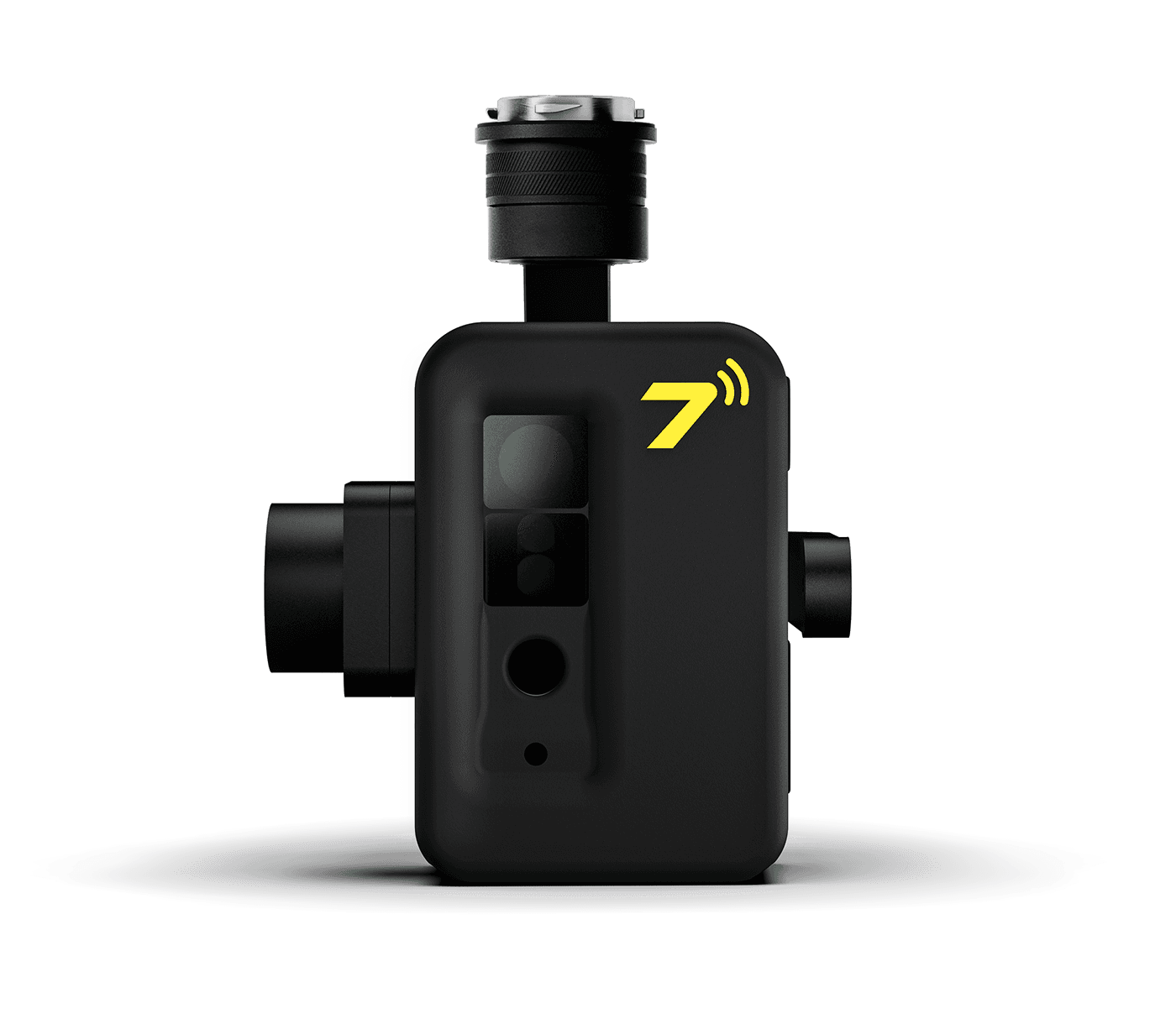
E-Field Sensor
Sensor Type
Electric (E-)Field
Capacitive
12%
200 kHz
13.565 MHz
15 mV/m to 1.2000 mV/m
Gimbal
Removable
Pitch +30° to -120°, Yaw: +320° to -320°
±1°
RF Communication
902 MHz
2-GFSK
0.2 W
Dipole Antenna
General
RF Communications
LTE PCB Antenna with SMA Connector
Active Mode
902 MHz
0.2 W
Power Supply
3S LiPo Battery 11.1V, 2200mAh
