Beyond Resistance: Understanding What Actually Compromises Lightning Protection Continuity
Conventional resistance measurements flag micro-cracks and corrosion as non-conformities. But under lightning stress, current bridges these minor irregularities. The system functions. What actually fails are air gaps—capacitive discontinuities that cause arcing and fire risk. Impedance-based measurement distinguishes between measurement noise and genuine functional failures per IEC 61400-24.

Dr. Mehdi Gholami
Head of Hardware Development

Table of contents
Share
The Measurement Problem Every LPS Technician Knows
You’ve seen it before. A continuity measurement returns a value above 1 ohm, flagging a potential non-conformity. The blade gets scheduled for closer inspection or repair. But when examined, the lightning protection system shows no structural damage. Just minor surface corrosion at an interface or micro-cracking in an aluminium profile.
Place this comparison within the broader workflow in the complete LPS inspection guide.
The reading wasn’t wrong. But was it meaningful?
This is the fundamental challenge with conventional low-voltage ohmic resistance measurements: they detect everything, including irregularities that have no bearing on whether the lightning protection system will actually perform its function when a strike occurs.
Understanding the difference between a measurement anomaly and a functional discontinuity requires examining what actually happens during a lightning event—and what the IEC 61400-24 standard is genuinely concerned with protecting against.
What Makes a Discontinuity Dangerous
Lightning protection systems fail when the conductive path cannot transfer current effectively during a strike. The critical question is: what conditions actually interrupt that path?
The answer lies in the distinction between resistive irregularities and capacitive discontinuities.
Resistive irregularities—such as micro-cracks within aluminium conductors or oxidation layers at connection interfaces—increase the measured DC resistance. Under low-voltage test conditions, these irregularities appear significant. However, under the high electrical stress of an actual lightning event, these minor gaps can be electrically bridged. The current finds its path. The system functions.
Capacitive discontinuities—physical air gaps that completely interrupt the conductive path—behave differently. These gaps require air ionisation to allow current passage, which produces electrical arcing, extreme localised temperature rise, and significant risk of fire or structural damage. This is what IEC 61400-24 defines as a loss of effective continuity.
The standard focuses on current-carrying capability and functional continuity of the lightning path—not on isolated resistance values that may spike due to surface-level imperfections.
Simulation Evidence: Resistive Elements Do Not Compromise Detection
To quantify this distinction, we modelled a 50-metre blade lightning protection system and introduced anomalies at various positions along the conductor path.
Test 1: Localised Resistive Element (100 Ω)
A pure resistive element of 100 ohms—representing micro-cracks or interface corrosion without any physical air gap—was placed at multiple locations along the blade. Each position was evaluated independently.
Figure 1: Impedance response with 100Ω resistive element at varying positions
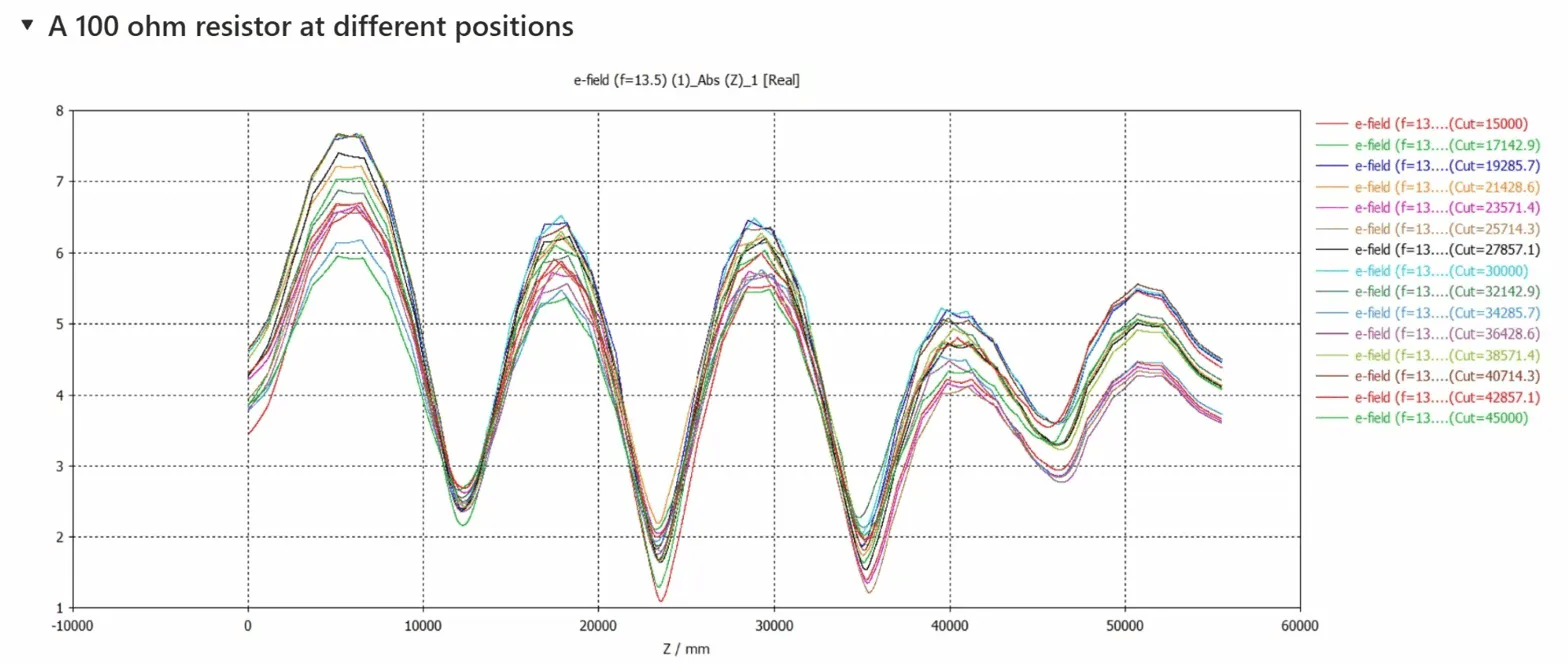
E-field response along blade length (Z/mm) with a 100Ω resistive anomaly introduced at positions ranging from 15m to 45m. Each coloured trace represents a different anomaly location. Despite the introduced resistance, all curves maintain consistent wave patterns, indicating the lightning protection system remains functionally continuous. The impedance-based method correctly identifies no functional discontinuity.
The result is clear: the introduction of a localised resistive irregularity does not materially influence the measurement outcome. In all simulated cases, the technique correctly identifies the lightning protection system as functionally continuous and operational.
This behaviour is consistent with IEC 61400-24, which focuses on the continuity and current-carrying capability of the lightning current path rather than on isolated increases in DC resistance.
Simulation Evidence: Physical Gaps Are Clearly Detected
Test 2: Capacitive Discontinuity (1 pF Air Gap)
When a capacitive discontinuity representing a physical air gap is introduced, the measurement response changes dramatically. A small capacitor (1 pF) was inserted to model the presence of a gap within the lightning current path at positions of approximately 21m, 23m, and 25m along the blade.
Figure 2: Impedance response with capacitive discontinuity (air gap) introduced
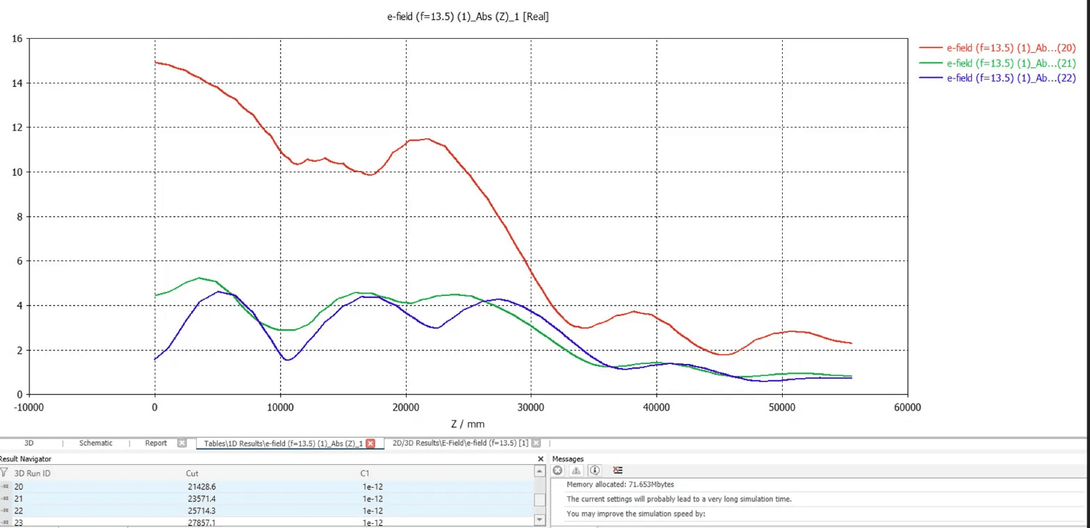
E-field response showing the effect of a 1pF capacitive element (simulating a physical air gap) at three positions. The red trace shows a pronounced deviation from baseline—a steep drop in signal amplitude beginning near the discontinuity location. This distinct signature indicates a loss of effective electrical continuity. The green and blue traces, representing gaps at different positions, show corresponding deviations at their respective locations.
The results show a distinct deviation in the measured impedance response, manifested as a pronounced drop in the curve. This deviation is a clear indicator of a loss of effective electrical continuity and is interpreted as a failure of the lightning current path.
In accordance with IEC 61400-24, such a capacitive discontinuity represents a functional degradation of the LPS, as it impairs the reliable transfer and dissipation of lightning current.
Field Validation: Consistent Detection Under Real Conditions
Simulation models require validation against physical reality. Field measurements were conducted on an operational blade with a confirmed break in the lightning protection system at approximately 22 metres from the root.
The discontinuity had been physically verified prior to testing. Using drone-mounted impedance measurement equipment, the inspection was repeated three times under identical conditions.
Figure 3: Repeated field measurements on blade with confirmed LPS discontinuity at ~22m
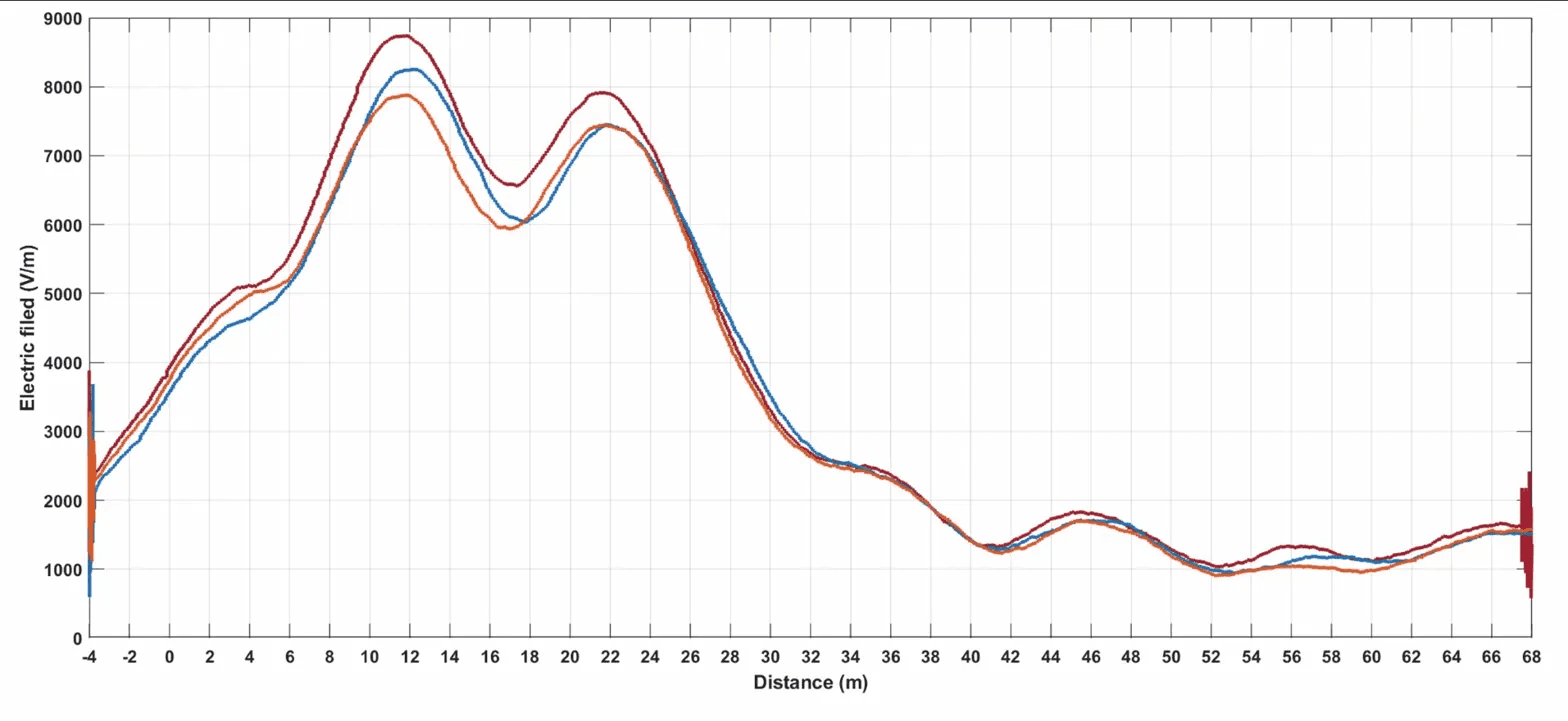
Electric field strength (V/m) measured along blade distance (m) across three independent measurement runs. All three traces show consistent peak detection in the region of 20–24m, corresponding to the physically verified discontinuity location. The close alignment of the three curves demonstrates measurement reproducibility and confirms the method’s reliability for identifying genuine losses of electrical continuity under operational conditions.
In all three measurements, the system detected the discontinuity at the same location. The results were consistent and reproducible, confirming the method’s capability to identify genuine losses of electrical continuity under real-world inspection conditions.
This repeatability matters. For technicians producing inspection reports that inform maintenance decisions, investment planning, and insurance assessments, measurement consistency is foundational to data trust.
Why Conventional Methods Produce Inconsistent Results
The limitations of low-voltage ohmic resistance measurement are well documented. ENERCON, in its technical guidance on rotor blade lightning protection inspection, explicitly acknowledges that micro-cracks in aluminium profiles and corrosion at contact interfaces frequently cause resistance values exceeding 1 ohm.
These readings are technically accurate. The resistance is elevated. But the elevated value does not indicate a functional discontinuity—it indicates a surface-level irregularity that would not impair current transfer during an actual lightning event.
ENERCON recommends high-voltage testing as an alternative, as the applied voltage can bridge micro-cracks and oxidation layers. However, that method requires mechanical intervention (inserting an external screw into the blade receptor) necessitating rope access with associated time, cost, and safety implications.
Measuring What Matters
Impedance-based measurement evaluates both the resistive and reactive components of the lightning current path under electrical stress conditions relevant to actual lightning events.
The practical implications for inspection technicians:
Fewer false positives: Minor resistive irregularities that do not compromise LPS function are correctly identified as non-critical.
Reliable detection of genuine failures: Physical discontinuities representing actual degradation are consistently identified.
Non-invasive execution: High-frequency signals bridge minor corrosion layers without physical contact—a capability independently confirmed in TÜV SÜD testing.
Reproducible results: Repeated measurements return consistent findings, providing the data confidence required for audit-ready documentation.
The Standard That Matters
IEC 61400-24 defines the requirements for lightning protection of wind turbines. Its focus is clear: ensuring the continuity and current-carrying capability of the lightning current path.
Methods that flag every resistive anomaly create noise. Methods that distinguish between surface-level imperfections and genuine discontinuities provide signal.
For technicians responsible for producing reliable inspection data, that distinction is everything.
This article is part of TOPseven’s technical knowledge series on lightning protection inspection methodology. For detailed measurement protocols or validation documentation, contact our technical team.
Return to the complete LPS inspection guide, review the standard behind the requirement, or compare the cost difference between methods.
Looking for more? Dive into our other articles, updates, and strategies


Expert Robotics.
Expert Knowledge.
Operator insights, technical deep-dives, benchmark data, and platform updates from the field. No fluff.