LPS Inspection for Wind Turbines: The Complete Guide
What LPS inspection for wind turbines actually requires — and why conventional resistance measurement misses the failures that matter. IEC 61400-24, electromagnetic wave diagnostics, and what genuine functional continuity means.

Florian Zimmer
Head of Operations
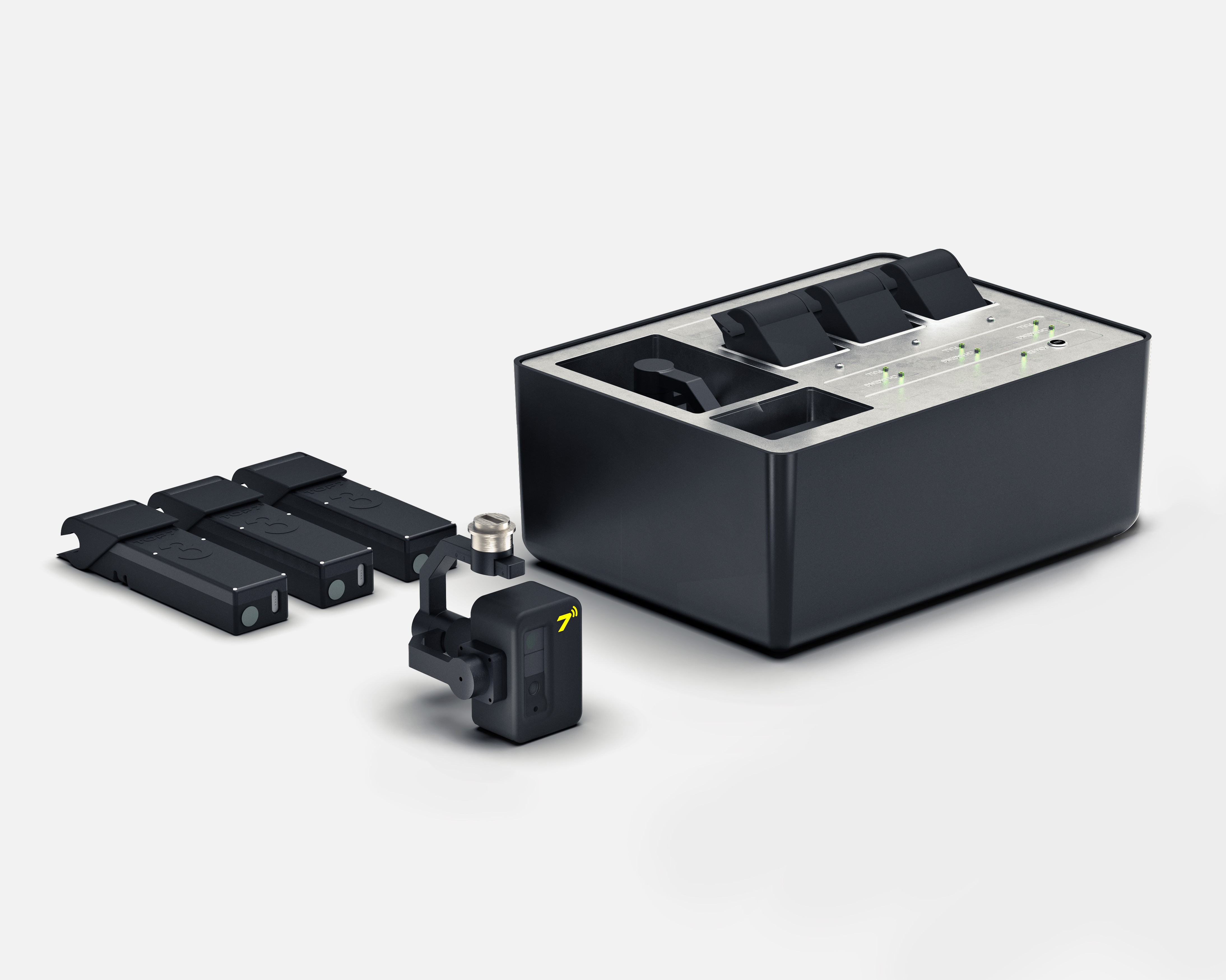
Table of contents
Share
LPS Inspection for Wind Turbines: The Complete Guide
Every rotor blade on a modern wind turbine is a lightning rod.
At hub heights above 100 metres, turbines do not just passively receive lightning. They trigger it. Their exposed position and considerable height make them prime targets for direct strikes. Without effective protection, a single event can cause damage to sensitive drive technology, structural delamination in the blade, and costly unplanned downtime.
The Lightning Protection System (LPS) is the barrier that prevents this.
Most guides tell you to measure resistance. Most of the industry does exactly that.
That is the problem.
This guide explains what LPS inspection actually requires: what the system consists of, what genuinely causes it to fail, why the metric the industry defaults to produces false results, and what a measurement approach grounded in physics actually looks like.
What the LPS in a wind turbine blade consists of
The Lightning Protection System is a conducting path designed to channel the electrical energy of a strike safely from the blade tip to the grounding system at the tower base. Its function is to prevent that energy from dissipating through the blade laminate, which causes delamination, internal fracturing, or total blade loss.
The system has several components that must all function together.
The tip receptor sits at the outermost point of the blade. It is the primary capture point for a strike. Wear, corrosion, and mechanical impact degrade it over the turbine's operational life.
The down conductor is a copper or aluminium cable running the full length of the blade interior. It connects the tip receptor to the root terminal. Cable fractures, kinks from blade flexion, and connection failures at mounting brackets are the most common failure modes in this section.
The root terminal connects the down conductor to the transfer system at the blade root. Arc damage at the root terminal is a reliable indicator that a real strike has already tested the system — and that the connection may have been compromised in the process.
The transfer system — a slip ring, carbon brush, spark gap, or spring coupling depending on the manufacturer — bridges the rotating blade assembly to the stationary nacelle and tower conductor. Each design has specific failure modes. Brushes wear down. Spark gaps widen beyond specification. Couplings lose contact pressure.
The tower grounding system dissipates the electrical load into the earth. Ground resistance above 1 ohm at the tower base indicates the grounding path is impaired.
Every component in this chain must function. A failure anywhere breaks the path. When the path breaks under real lightning stress, the energy finds another route through the blade structure.
Why LPS inspection is not optional
A functioning lightning protection system is required by law. It is also economically indispensable.
Insurance coverage and OEM warranties are increasingly conditional on documented, regular inspection. Following the South Australian grid event in 2016 — triggered by 80,000 lightning strikes and the failure of wind farms without adequate LPS — operators in multiple markets faced regulatory consequences for uninspected systems. The financial exposure from an undocumented LPS failure far exceeds the cost of a compliant inspection programme.
What IEC 61400-24 actually requires
IEC 61400-24 is the governing standard for lightning protection of wind turbine generators. It defines design requirements, test procedures, and inspection intervals.
Most operators and service providers read it as a document about resistance thresholds. It is not. Its focus is the continuity and current-carrying capability of the lightning current path. The question the standard is asking is whether the system can transfer and dissipate lightning current reliably. That is a functional question. Not a resistance question.
The inspection intervals it prescribes:
Level I and II systems, rated at 200 kA and 150 kA respectively, require a visual inspection annually and a full electrical inspection every two years. Level III and IV systems require a full inspection every four years. Post-installation testing is mandatory before commercial operation. Post-repair testing is mandatory after any work that touches the LPS or blade interior
High-risk sites — elevated terrain, coastal exposure, documented high lightning density — should be inspected more frequently regardless of system rating.
These are not recommendations. They are requirements.
The measurement problem no one in the industry talks about
A resistance reading above 1 ohm triggers an inspection flag. The blade gets scheduled for closer examination or repair. When examined, the technician often finds no structural damage. Just surface corrosion at a connection interface or micro-cracking in an aluminium conductor profile.
The reading was technically accurate. The resistance was elevated.
But was the flag meaningful?
This is the fundamental limitation of conventional low-voltage DC resistance measurement. It detects everything — including irregularities that have no bearing on whether the LPS will perform its function when a strike actually occurs.
There are two fundamentally different types of anomaly in an LPS. Understanding the difference determines whether your inspection data is signal or noise.
Resistive irregularities — micro-cracks in aluminium conductors, oxidation layers at connection interfaces — increase measured DC resistance. Under low-voltage test conditions, these look significant. Under the high electrical stress of a real lightning event, the current bridges these minor gaps. The system functions. Flagging them as non-conformities produces false positives that drive unnecessary inspection campaigns and premature repair decisions.
Capacitive discontinuities — physical air gaps that completely interrupt the conductive path — behave differently. These gaps require air ionisation to permit current passage. That ionisation produces arcing, extreme localised heat, and genuine risk of fire or structural damage to the blade. This is what a functional LPS failure looks like.
The question every inspection must answer is not "does this blade have a resistance anomaly?" It is: "does this blade have a physical air gap that will cause arcing under real strike conditions?"
Those are different questions. Conventional resistance measurement cannot reliably distinguish between them.
ENERCON acknowledges this directly in its own technical guidance on rotor blade LPS inspection. Micro-cracks in aluminium profiles and corrosion at contact interfaces frequently produce resistance readings above 1 ohm that do not represent a functional discontinuity. ENERCON recommends high-voltage testing as an alternative, because the applied voltage bridges minor resistive irregularities and reveals genuine gaps. The limitation is that high-voltage testing requires mechanical access to the blade receptor — meaning rope access, with all the time, cost, and safety implications that entails.
What electromagnetic wave diagnostics reveal instead
TOPseven's BEAT sensor approaches LPS inspection from an entirely different physical principle.
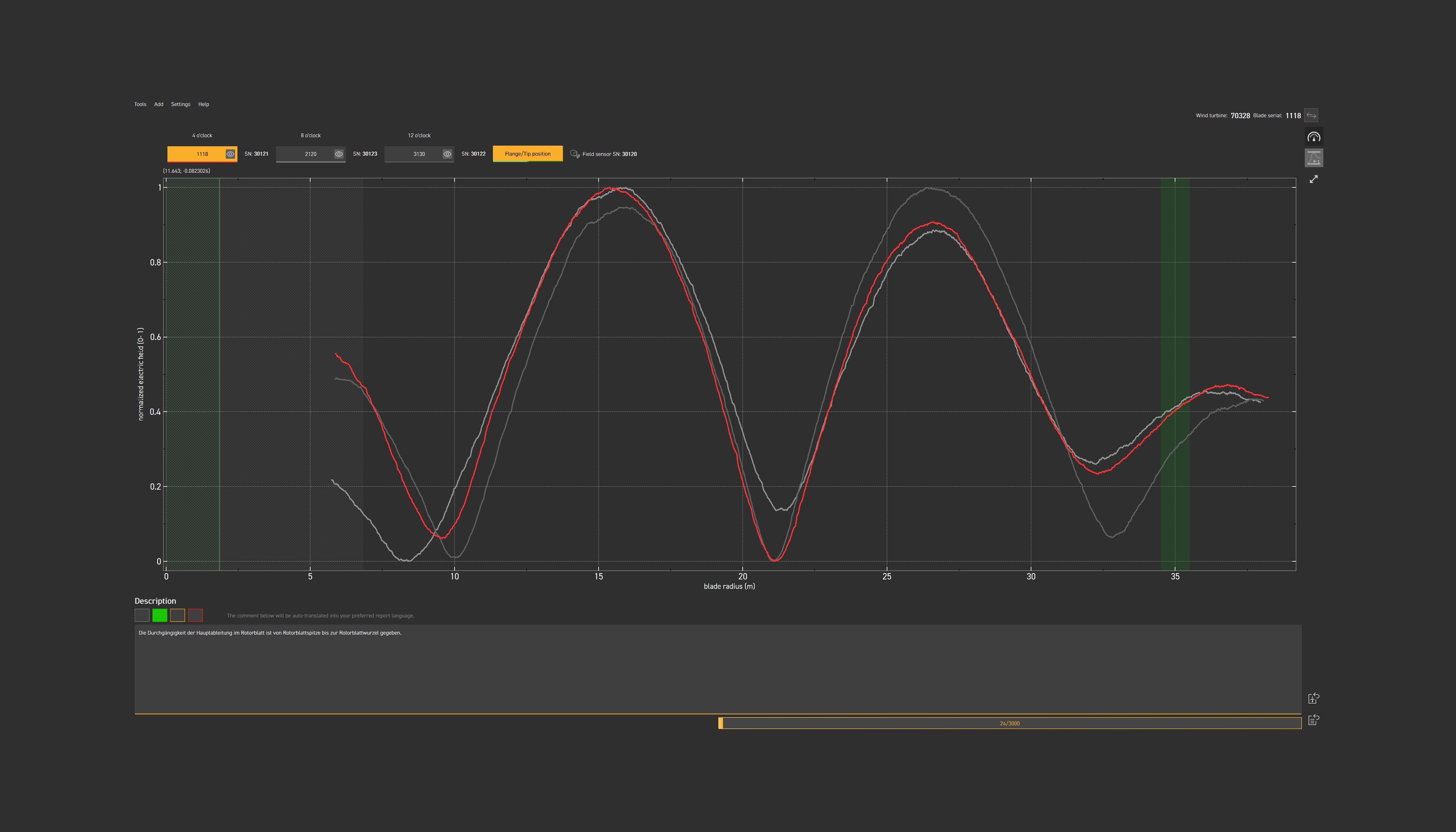
Instead of injecting a low-voltage DC signal and measuring how much resistance the circuit presents, BEAT uses high-frequency electromagnetic waves. When the lightning protection system is intact, the signal travels to the blade tip and reflects back. The superposition of the forward and reflected waves generates a characteristic standing wave with a period of approximately 11 metres.
This standing wave is the system's fingerprint.
An intact LPS produces a complete, uniform wave pattern. Deviations from that pattern — premature termination, characteristic disturbances at a specific location — indicate where the continuity of the system is genuinely compromised.
The distinction between resistive anomaly and real failure is built into the physics of the method. High-frequency signals bridge minor corrosion layers and micro-cracks without registering them as failures. This capability was independently confirmed in TÜV SÜD testing. What the method does detect clearly is a physical air gap — a capacitive discontinuity that causes a distinct, reproducible deviation in the wave response at the location of the gap.
This is the measurement that IEC 61400-24 is actually asking for: evidence of functional continuity along the lightning current path. Not a resistance value that may spike due to surface corrosion and have nothing to do with how the system performs under strike conditions.
Simulation and field evidence
To validate the distinction between resistive and capacitive anomalies, TOPseven modelled a 50-metre blade LPS and introduced anomalies at multiple positions.
When a 100-ohm resistive element — representing micro-cracking or interface corrosion without a physical air gap — was introduced at multiple positions along the conductor, the measurement correctly identified the system as functionally continuous in every case. No false positive.
When a 1-picofarad capacitive element — simulating a physical air gap — was introduced at positions of approximately 21, 23, and 25 metres along the blade, the response changed immediately. A pronounced drop in signal amplitude appeared at each gap location. Genuine failure. Correctly detected.
Field validation followed on an operational blade with a confirmed physical break in the LPS at approximately 22 metres from the root. The discontinuity was physically verified before testing. Using the drone-mounted BEAT sensor, the inspection was conducted three times under identical conditions. All three measurements detected the discontinuity at the same location. The curves aligned closely across all three runs.
That reproducibility matters. It is the basis for audit-ready documentation. A result that varies between operators or conditions cannot serve as the foundation for a maintenance decision, an insurance assessment, or a regulatory submission.
The method was also validated at scale: 40 different wind turbines in a single wind farm were inspected using the electromagnetic wave approach. All showed an almost identical signature in the propagation of the electric field. A defective system would have produced a deviating pattern immediately visible in comparison.
The reference database: what consistency enables
The consistency of measurement results within a turbine type enables something that conventional resistance measurement cannot: the systematic development of type-specific reference signatures.
Each turbine type has a characteristic fingerprint — the standing wave pattern that describes a fully functional LPS for that specific design. As TOPseven builds its reference database across turbine types and installations, each inspection can be evaluated directly against that type-specific baseline. Deviations from the expected pattern become visible before they lead to failure.
This is what preventive maintenance in LPS inspection actually looks like. Not a resistance reading compared to a generic threshold. A system-specific electromagnetic signature compared to a verified reference for that design.
LPS inspection as a dedicated mission
LPS inspection with the BEAT sensor is a dedicated mission. It is not combined with the visual blade inspection in a single flight. Each inspection type is a separate operation with its own mission objective, protocol, and output.
This matters for planning. Treating LPS inspection and visual inspection as separate scheduled activities — rather than assuming they can be bundled without operational consequence — produces cleaner data, clearer accountability, and compliant documentation for each inspection type independently.
Both missions belong in your annual maintenance schedule. Neither replaces the other. The data they produce is complementary: visual inspection identifies surface damage and structural concerns. LPS inspection confirms that the system protecting the blade from a strike is electrically functional. One tells you the condition of the blade. The other tells you whether the blade is protected.
What inspection intervals and planning should look like
For fleet operators, LPS inspection planning should be built around three inputs.
First, IEC 61400-24 intervals. Level I and II systems need a full electrical inspection every two years. That is the non-negotiable floor.
Second, site lightning risk. Ground flash density, historical strike records, and proximity to elevated terrain or coastlines should determine whether more frequent inspection is warranted above the IEC minimum.
Third, triggered events. A confirmed lightning strike at the site, an anomalous SCADA signal following a storm, or visual evidence of arc damage at the blade root are all grounds for unscheduled inspection before the next planned cycle.
Inspection data should be stored and structured for comparison across cycles. A single electromagnetic signature tells you whether the LPS passed today. A series of signatures across successive inspections tells you whether the system fingerprint is changing — and whether the change indicates emerging degradation before it becomes a failure.
That is the information that supports proactive decisions rather than reactive ones.
What is LPS inspection for wind turbines? LPS inspection for wind turbines verifies that the Lightning Protection System — the conductive path from each blade tip receptor through the internal down conductor, across the transfer system, and to the tower grounding — is intact and capable of conducting a lightning strike without arcing or structural damage. A complete inspection confirms functional continuity of the lightning current path, not just the presence of a conductive element.
How often should LPS be inspected on wind turbines? IEC 61400-24 requires a full electrical inspection every two years for Level I and II systems, and an annual visual check. Level III and IV systems require a full inspection every four years. Inspections are mandatory after installation and after any work involving the LPS or blade interior. Sites with high lightning activity or exposed terrain should be inspected more frequently regardless of system rating.
Is resistance measurement enough for LPS inspection? Conventional DC resistance measurement has a recognised limitation: it cannot distinguish between resistive anomalies — surface corrosion or micro-cracks that elevate resistance but do not impair system function under real lightning stress — and physical air gaps that cause arcing and represent genuine failure. The result is false positives that drive unnecessary inspections and repair decisions. TOPseven's BEAT sensor uses electromagnetic wave measurement to identify genuine functional discontinuities without being misled by resistive irregularities. This aligns with IEC 61400-24's focus on functional continuity and current-carrying capability, not resistance values in isolation.
What is the electromagnetic wave method for LPS inspection? The electromagnetic wave method injects a high-frequency signal into the LPS and analyses the wave response along the blade. An intact system produces a characteristic standing wave with approximately 11-metre periods — a unique fingerprint for that system. Physical air gaps cause distinct deviations from this pattern at the location of the discontinuity. Resistive irregularities such as surface corrosion do not affect the wave pattern. The method is non-invasive, requires no dismantling, and produces reproducible results validated by TÜV SÜD.
What is the difference between resistive and capacitive LPS discontinuities? A resistive discontinuity — micro-cracking in an aluminium conductor or oxidation at a connection interface — increases measured DC resistance. Under real lightning stress, the high voltage bridges this type of gap, and the system functions. A capacitive discontinuity is a physical air gap. It requires air ionisation to conduct current, which produces arcing and extreme localised heat. This represents a genuine functional failure of the LPS. Electromagnetic wave measurement distinguishes between the two. Conventional DC resistance measurement often cannot.
Can you combine LPS inspection and visual blade inspection in one drone flight? No. LPS inspection with the BEAT sensor and visual blade inspection are separate missions with distinct objectives, protocols, and outputs. Both are required in a comprehensive maintenance programme. Visual inspection identifies surface damage and structural conditions. LPS inspection confirms the electrical functionality of the lightning protection path. Neither replaces the other and each is planned as an independent operation.
Looking for more? Dive into our other articles, updates, and strategies


Expert Robotics.
Expert Knowledge.
Operator insights, technical deep-dives, benchmark data, and platform updates from the field. No fluff.